Losmandy G11 One Piece Worm Block Test Results


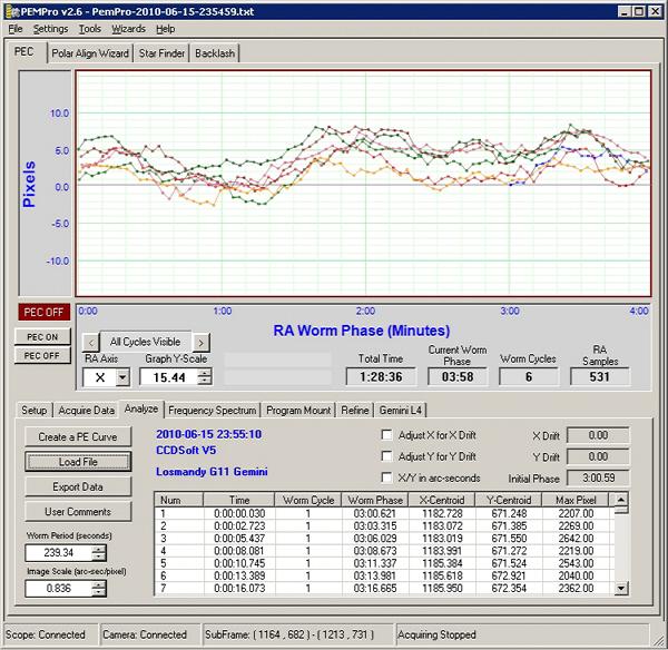
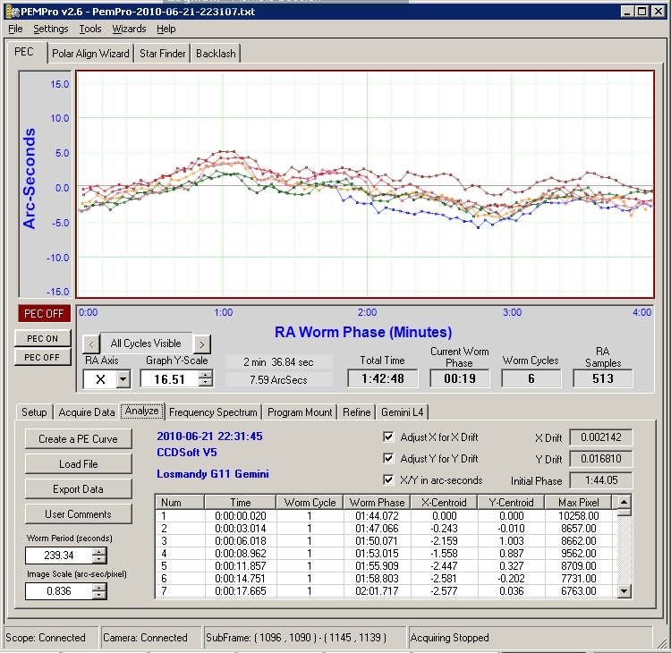
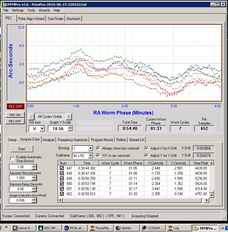
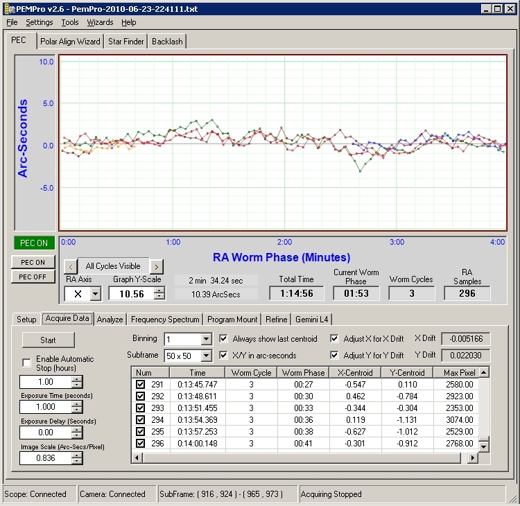
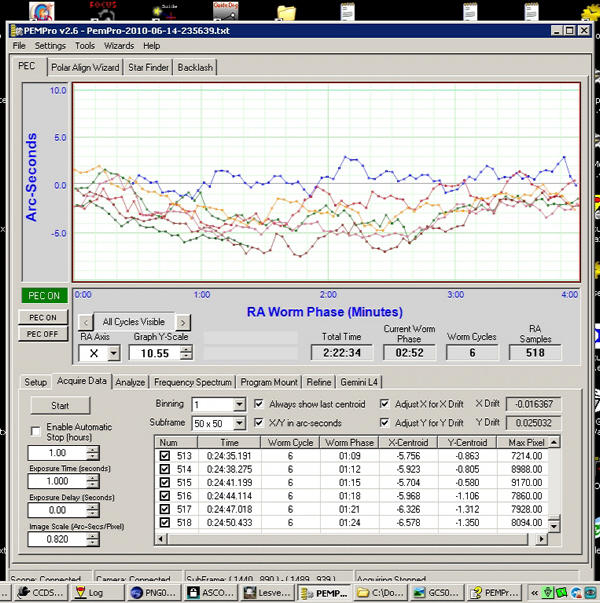
  Several nights of testing were performed to evaluate the new block design. Below are the before and after results using PemPro that was used to measure and plot the performance results. My mount is using the brass high precision worm and though this was an improvement over the high precision steel worm that came with it originally, I was never able to get the performance I was expecting with the brass. But, it didn't effect my imaging so I lived with it. That was until I read in the Yahoo Losmandy users group that a one piece worm block was being released. So I quickly bought one knowing well that this design hasn't been proven. But, like so many in that group, tinkering with this mount is easy and Losmandy has a reputation of superb machining.

Some of my expectations for purchasing the new block design were:


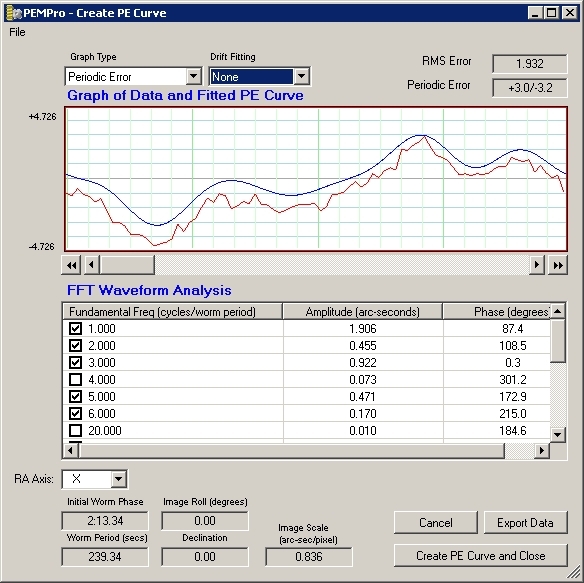
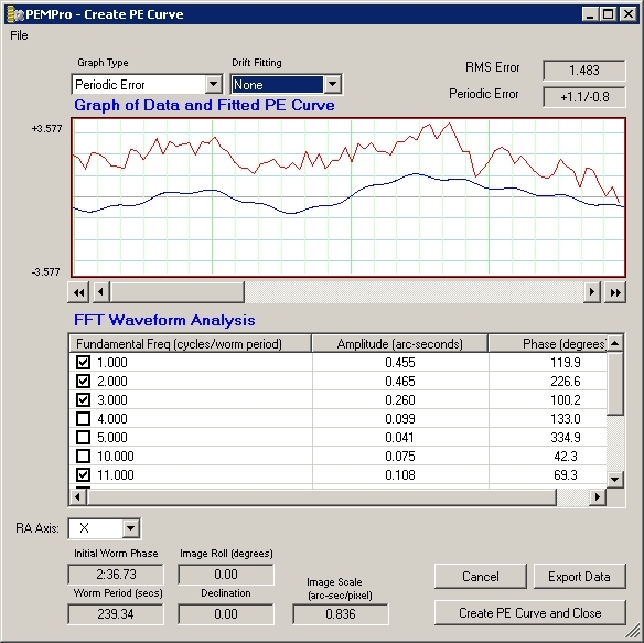
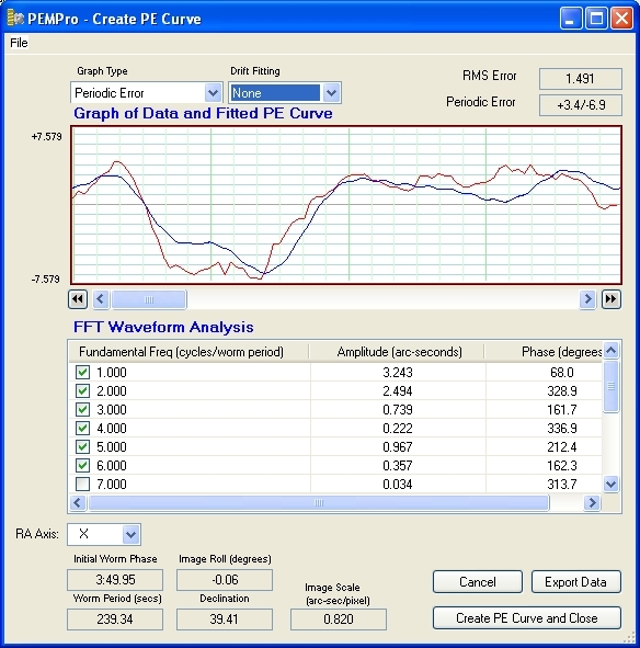
Note: PemPro does allows you to fine tune the PEC profile by adjusting drift and delays. I decided to present the data unmodified for comparisons. Each persons mount will behave differently with fine tuning which is why I left these results untouched.

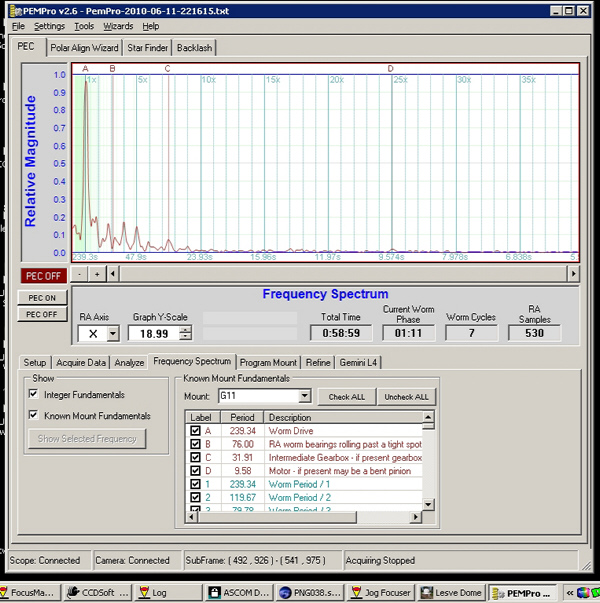
Before Upgrade Results
(Clicking on the PemPro images will open a larger version to better see the details)

This is the typical profile of my mount using the stock G11 block with the high precision brass worm. The peak measurements of the worms profile. To get peak-peak you will have to multiply the peak value by 2.
A graph displaying the peak profiles. Note the 76 error near 'B' is low compared to the peak of the PE. The 2X fundamental will be a matter of concern after the upgrade.
After Upgrade Test Results

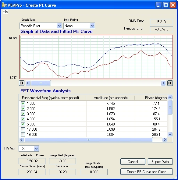
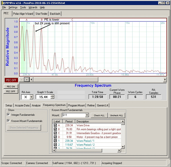
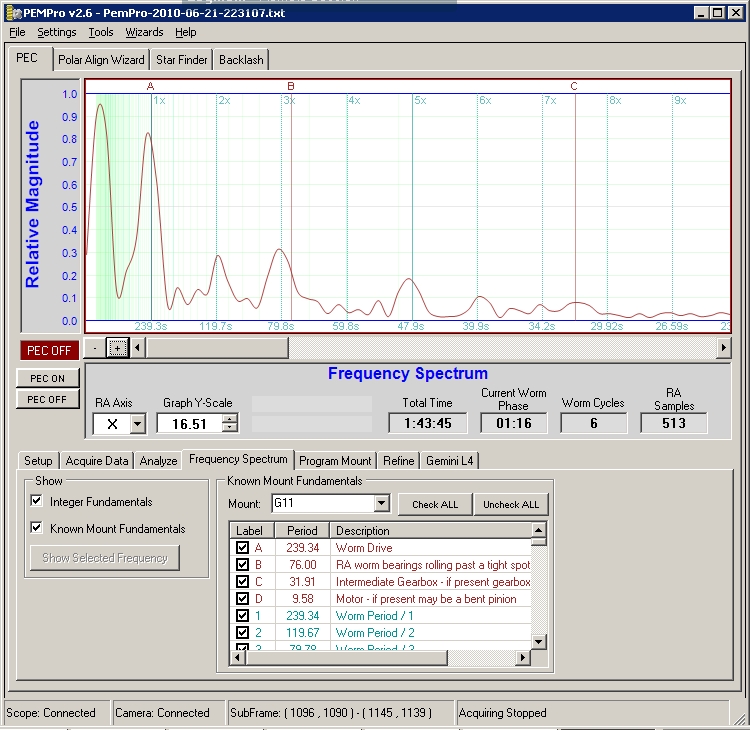
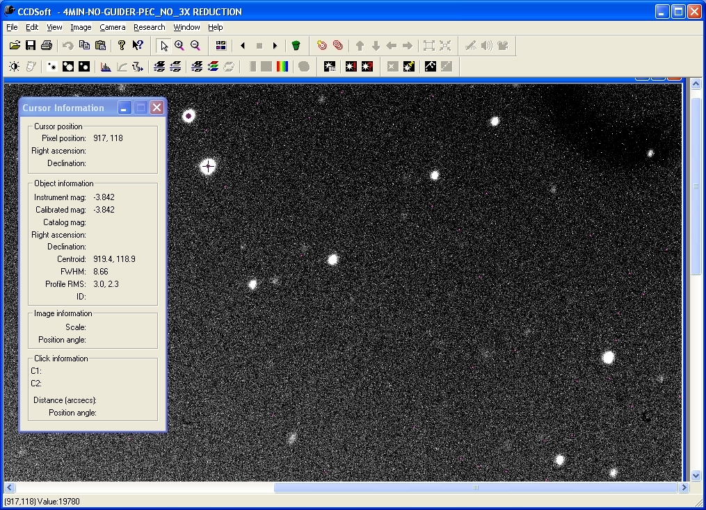
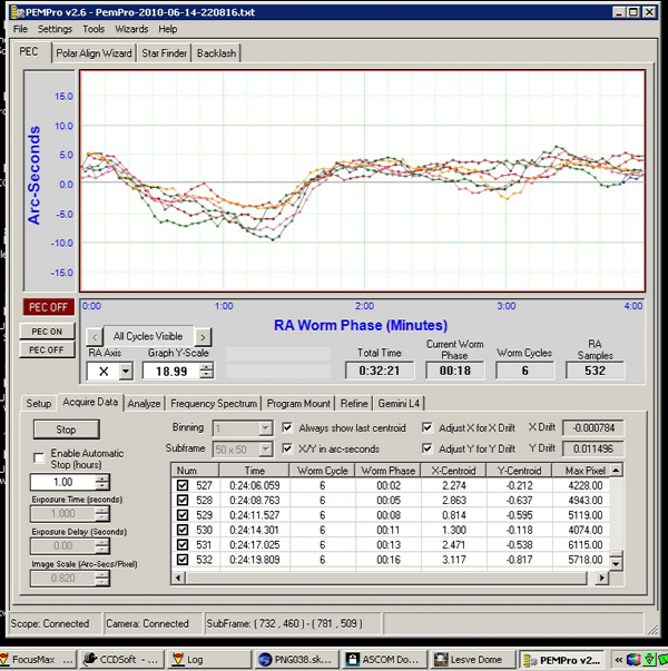
Round 1 - Does this block perform as good as it looks?

After the new block was installed and adjusted, 6 worm cycles were measured using PemPro and the results displayed. Plots of the peaks shows the 2X peak has become very defined compared to the 'before' profile.
Displaying the peak values it's evident the PE has been reduced almost 50% as well the infamous 76 second error. But the 2X fundamental has almost doubled.
Uploading the newly created PEC profile additional worm cycles were measured. The 2X peak has been removed using PEC. But why did it grow after the upgrade? Not everyone used PEC so this may become an issue.
The FFT analysis table shows low PE as well as the 2X peak reduced when using PEC
Round 2 - Time to investigate

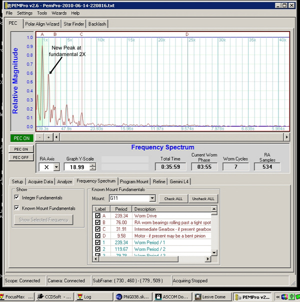
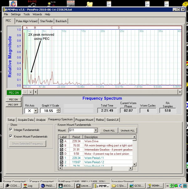
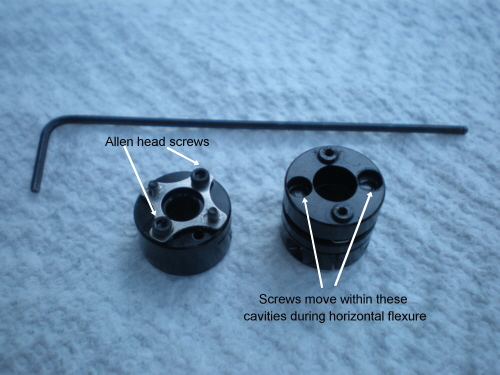
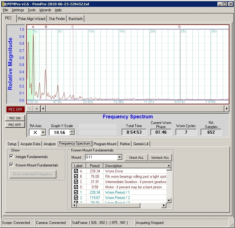
  Attempting to isolate the cause of the 2X peak growth, the block assembly was taken apart and carefully reassembled. I couldn't find anything that may have cause this increase in the 2X spike.

PE results after 6 worm periods. PE improved but the 2X peak still exists.
Notice the PE improvement of 1.440 (down from 3.24 from the lst run) and the 2X error is reduced but its contribution is now as much as the PE.


Out with the old and in with the new
  At this point I developed a theory that it's the new coupler design that may be causing this. Not that the design is at fault but our installation practices need to be revised with this new design.
  Inserting the worm by itself and manually rotating it I could feel no binding. When only the gearbox was installed and the coupler tightened to the worm shaft, a soft 'pulsating' movement could be felt when turning the worm and gearbox assembly. I attributed this to the coupler joints flexing due to minor shaft collinear misalignments.

Round 3 - Time to develop a new alignment strategy to use with the new block!


Turning the worm and gearbox (servo motor removed) a pulsation could be felt. If you can feel a resistance then it's sure to become part of the worm tracking profile. With the gearbox slightly loosened and held vertical I rotated the worm to allow the gearbox to center itself. You may need to make minor box movements to minimize any 'pulsations'. Once done gently snug the gearbox standoffs. Also loosen the coupler collar on the gearbox side to allow for any coupler relaxation in case the gearbox moved along the horizontal axis. Don't forget to retighten!
Ruland Disk Coupler Exploded view of the Ruland disk coupler. This design doesn't allow much collinear movement compared to the Oldham coupler so worm to gearbox shaft alignment becomes more critical.
Time to test the theory

Round 4 - New shaft alignment results measurements

Six worm cycles were measured after new alignment procedure. The 2X peak is reduced substantially.
PE error has gone up slightly but the 2X peak has gone down. Looks like I'm on the right track.
Fine tuning the alignment

Round 5 - Fine tune the coupler to gearbox alignment.

To eliminate a faint 'pulsation' that came back after tightening the gearbox studs I had to shim the gearbox. After 3 more attempts at adjustments and retesting I discovered the tabs on the gearbox body were pressing up against the mounting plate when the mounting studs were tightened. This must have skewed the gear body slightly causing the shaft alignment to change. Shimming using a flat washer under each ear was enough to raise the tabs a little to completely eliminated the 'pulsation'. Seven worm cycles were measured.
Peak plots after shimming gear motor to eliminate the 'pulsation'. The 2X peak appears to be affected by mechanical alignment in the gear/worm area as the results show in these measurements. PE has improved since the first alignment method and the 2X peak is down.
With PEC enabled 3 worm cycles were measured. PE peak is low and approaching the levels of the gearbox and the infamous 76 sec. error.
A very respectable PE for a mount in this price range.
This is an unguided, uncalibrated, unfocused but PEC enabled 4 minute exposure taken through an 1857 mm F/L OTA with an image scale of 0.83 arcsec/pixel. This covers one worm cycle. I expected to see some elongation due to no auto guiding but I was very surprised to see how good tracking is without auto guiding enabled. Using CCDSoft the stars (marked by the +) profile RMS can be measured to give an indication of the axis differences. Ideally they should be the same under perfect conditions. Even when auto guiding these numbers will vary slightly between X&Y so these unguided values are pretty good. Another image with a different star selected to display its profile.


Before and After Results

Before - PE profile with the stock G11 worm assembly with the high precision brass worm and no PEC applied
Note that there are no drift fitting applied to these before and after results to purposely show the raw results. Most graph examples posted on the web have them applied and the numbers appear much lower.
After - PE profile with the new one piece worm block using the original brass worm aligned using the method described. No PEC applied. While the slopes between the old and new designs look similar (same worm), note the Y scale between the two. The new block results scale is only +/- 4.7 arc seconds.

© 2010 Michael A. Siniscalchi