For the longest time it was believe that the 76 sec error was caused by the 2 separate worm block not fully aligned thereby causing some
uneven rotational friction in the ball bearing race. Reported error peaks ranged from under 1 arc/sec to over 4 arc seconds. The variances most likely due to differences in alignment methods used by each owner. For visual use this isn't an issue but for imaging it can cause guider problems because the error was large enough to possibly register in star shape depending on image scale. And the fact that the peak didn't occur on a fundamental worm frequency meant it couldn't be guided out with a trained PEC profile.
After market worm blocks milled out of a single piece of metal have shown the 76 error is reduced to almost being completely gone so the alignment theory seems plausible but there is more than one reason as we'll soon find out.
Before I installed the Losmandy one piece worm block the typical 76 sec error on my mount averaged 1.6 arc seconds (no PEC) with the 2 piece block being carefully aligned. Also, with the peak not on a fundamental frequency line it couldn't be removed successfully with PEC programming. With the new Losmandy one piece block, the 76 error was reduced to .9 arc seconds (no PEC) and the peak shifted to the 80 second fundamental mark so it was successfully reduced substantially to .260 arc seconds with PEC enabled. This 76 error reduction adds credence to block alignments having an effect and the new block design has certainly improved that in both amplitude and fundamental timing.
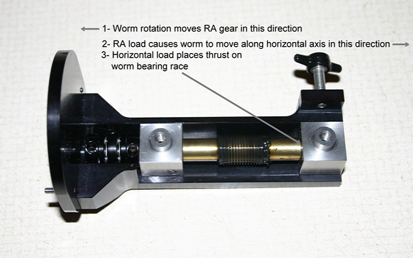
Why was the 76 sec error still present now that the worm blocks were aligned on a common platform though the amplitude was reduced and timing shifted slightly? Let's step back and look at what is happening when the RA gear is moving under load and normal speed. In the diagram below it becomes obvious that due to load reactions on the RA worm gear the worm will naturally push opposite the resistive load (where have I heard this before?). This horizontal movement places an axial load (thrust) on the worm bearing race. This thrust must be causing side pressure on the balls within the race to ride up against the race groove walls. Let's move to the next section to see what is happening with the balls when the worm turns.
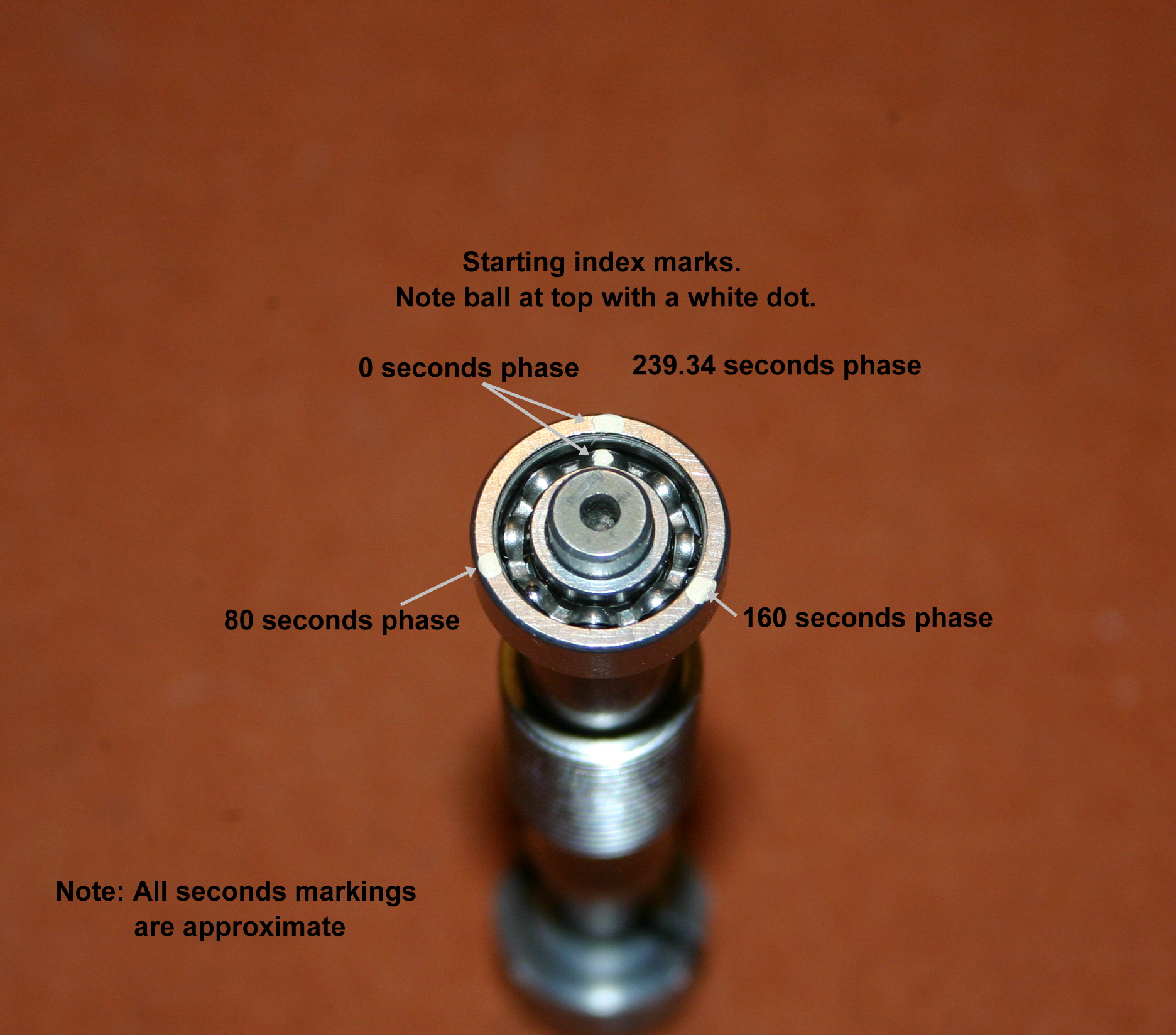
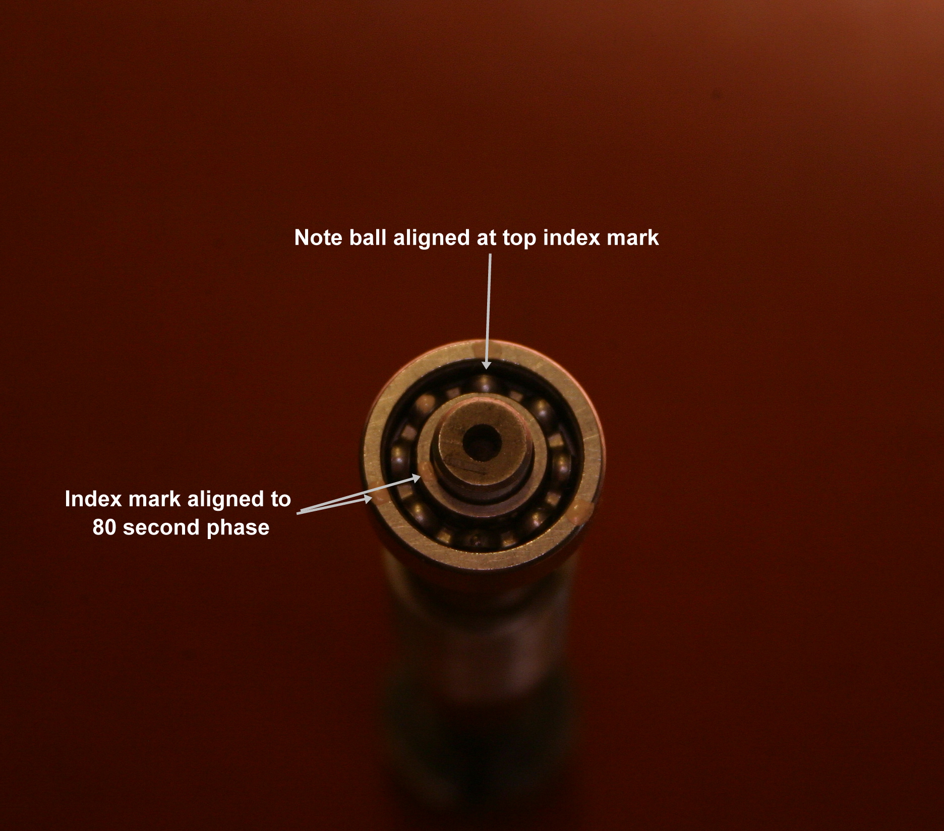
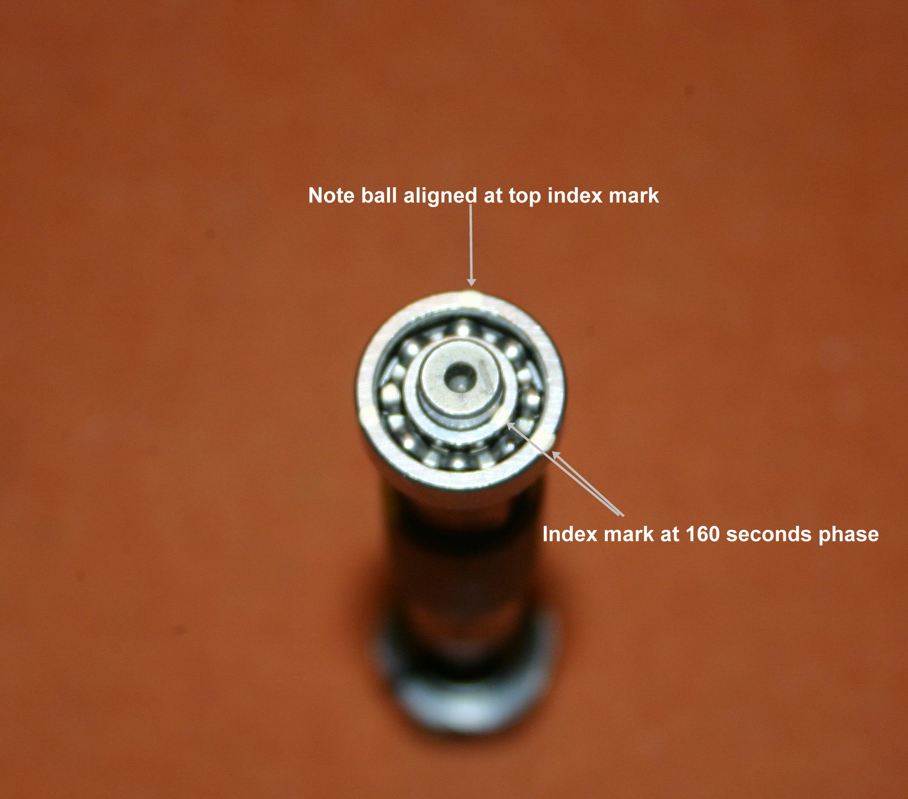
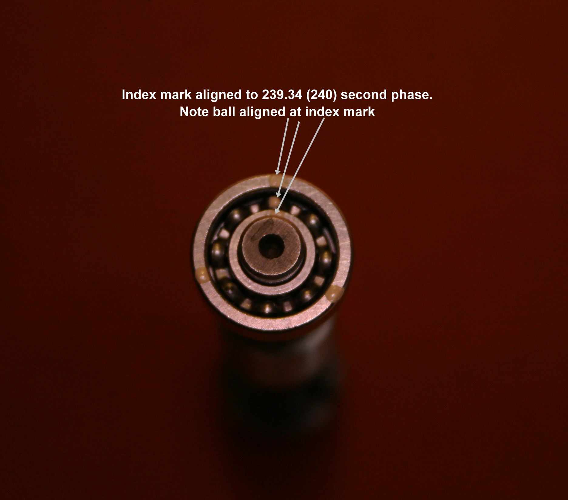
Ball bearing race to shaft relation during one worm cycle
The 76 error has shifted to the 80 second fundamental with the new worm block. The 76 error (now at 80 seconds) should occur 3 times per revolution which takes 239.3447 seconds.
The images below are an insight as to what is happening within the ball bearing race during a worm revolution.
(Clicking on the images will open a larger version to better see the details)